
Electron configuration can be expressed in the form of an orbital diagram, where each orbital refers to a subshell and one-headed arrows are used to depict electrons. Each orbital can accommodate only 2 electrons.
- s: 1 orbital (2 electrons maximum)
- p: 3 orbitals (6 electrons maximum)
- d: 5 orbitals (10 electrons maximum)
- f: 7 orbitals (14 electrons maximum)
Rules to Observe When Drawing Orbital Diagrams:
- Pauli Exclusion Principle: no two electrons in an atom can have the same four quantum numbers. Basically this means that electrons must have opposite spins.
- Hund’s Rule: the most stable arrangement of electrons in subshells is the one with the greatest number of parallel spins
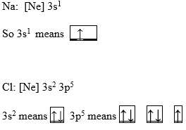
Examples:
Paramagnetic and Dimagnetic:
Paramagnetic: describes electron spins (arrows) that are “parallel” to one another or spinning in the SAME direction. This occurs with UNPAIRED electrons.

Dimagnetic: describes electron spins (arrows) that are spinning in “di” or TWO OPPOSITE directions. This occurs with PAIRED electrons (Pauli Exclusion Principle)